The Final Touches
- Muhammad Abdullatif
- Nov 26, 2023
- 2 min read

Over the past two weeks, team 16 has completed Milestone 3. As of November 18, the final three tasks had been completed. Comprehensive analyses were conducted, including free body diagrams, bolt shear, deflection calculations, and FEAs on the 3D model. Out of the three, the first and second tasks involved completing FEAs on replicating cylinder force, comparing it with the stress and strain calculations, and generating a pressure simulation on the 3D model. The outcome was favorable, showcasing a maximum deflection of 1.3 inches and a shear force an impressive 50 times lower than the material's yield strength. Notably, the FEAs unveiled no stress or strain concerns besides minimal deformation attributable to the cylinder force. As for the final task, all information, including the full design calculation package, is ready for validation by the client, HMH.
The final design, pictured in Figure 1, implemented by the team is a split manifold specifically chosen to address key issues related to cost, production efficiency, and manufacturing capabilities. The manufacturing process for the split manifold closely mirrors that of the full manifold, with the added advantage that multiple parts can be produced simultaneously, optimizing the overall production efficiency. The partitioned manifold will be held together by 8 bolts that pass through it. This aligns with HMH's preference to manufacture the split manifold design.

Figure 1. Final CAD Design
To accommodate the vendor's capabilities, the split manifold design incorporates chamfers instead of radii, ensuring compatibility and ease of manufacturing. The initial manufacturing issues, specifically with the Hot Isostatic Pressing (HIP) process causing internal ports to shift, have been effectively addressed in the final design. Adopting additive manufacturing was a key decision due to its ability to handle complex geometries and mitigate the problems encountered in the earlier manufacturing stages.
The team has compiled many key analytical results that demonstrate the successes and strengths of the design. The shear stress and deflection calculations on the bolts for the current split design have been conducted. The outcome showed a maximum deflection of 1.3 inches and a maximum shear force of 925 pound-force. In addition, an FEA was completed on the full assembly to compare with the bolt calculations and to ensure that stress and deformation remain minimal. The results of the FEA shown in Figure 3 depict that the calculated deflections were accurate and quite conservative.
All analyses of the manifold will be conducted and completed before the start of the Spring 2024 semester. The shear and deflection calculations for the bolts are completed (as shown in Figure 2) and the FEA of the cylinder force, as seen in Figure 3. The FEA for the pressure simulation to replicate subsea environments is ongoing but will be completed before the start of the second semester. The team plans to validate the full design calculation package with the sponsor, HMH, before starting Capstone II. Most of the analysis of the device has been completed, but it is crucial in the engineering field to have a third party review any analysis work before confirming the validity of the product. This will allow the team to create the technical production drawings early next semester to be able to execute the design swiftly.

Figure 2. Shear & Deflection for Bolts Results
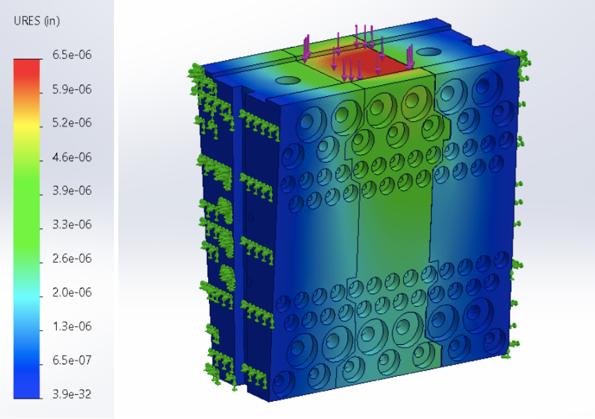
Figure 3. FEA of Device Featuring Hydraulic Cylinder Force


Comments