Back & Better
- Muhammad Abdullatif
- Feb 4, 2024
- 2 min read

Throughout the break, Team 16 maintained frequent meetings with HMH. The sponsor requested that the CAD be changed to allow for a higher load shoulder in order to distribute the weight more evenly across the manifold. The new CAD design (shown in Figure 1) includes an S-shaped interior port, allowing the load shoulder to be deeper and wider while avoiding the manifold split. In addition, the team has started looking for post-processing vendors to help with extrusion honing. The team is still on pace and will begin preparing technical drawings for prototype orders.
After receiving assistance and constructive feedback from our professor and sponsor, Team 16 completed more accurate FEAs. To improve our analysis, the team is modifying our FEA by changing the boundary conditions and disturbing the applied downward force on each load shoulder in order to reflect a more accurate model.

Figure 1: Highlighted S-Shape Port
Our goal is to gain final approval for the improved FEAs in the following week. Once this is completed, we will request approval for an undersized model of the manifold produced and assembled at Laser Welding Solutions. We seek to complete the technical drawings and process the order of the initial prototype.
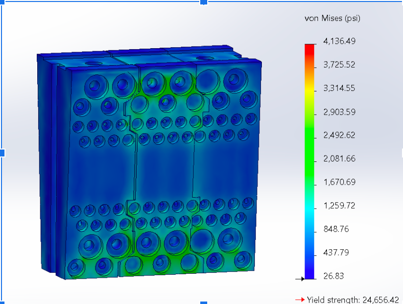
Figure 2: von Mises FEA

Figure 3: Von Mises FEA Split
In the coming two weeks, our team anticipates a potential problem with generating FEAs that precisely replicate the real-world stresses and forces that the manifold is expected to endure. These forces include the net downward force, the piston force applied to the load shoulder, and the spring force. As a backup plan, if we face problems with the FEAs, we will contact HMH's FEA specialist for guidance in correcting the FEAs. This proactive approach demonstrates our dedication to thoroughly preparing and successfully implementing our project goals.


Comments